Centrifugal pumps, in general, are too familiar to us. They appear everywhere, from home to industrial production. But few people know the structure of centrifugal pumps? And how can they pump water?
This article does not dissect the problem of centrifugal pump structure. But, hopefully, the paper will help a little for those of you who have been using this pump line and have specific knowledge to understand them better. From there, know how to handle problems that arise during use.
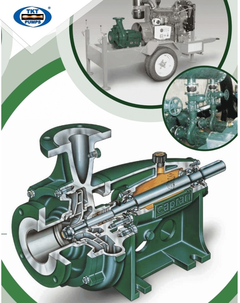
Centrifugal pump construction

Although centrifugal pumps have many different types, such as
-
- Horizontal Centrifugal Pump
- Vertical shaft centrifugal pump
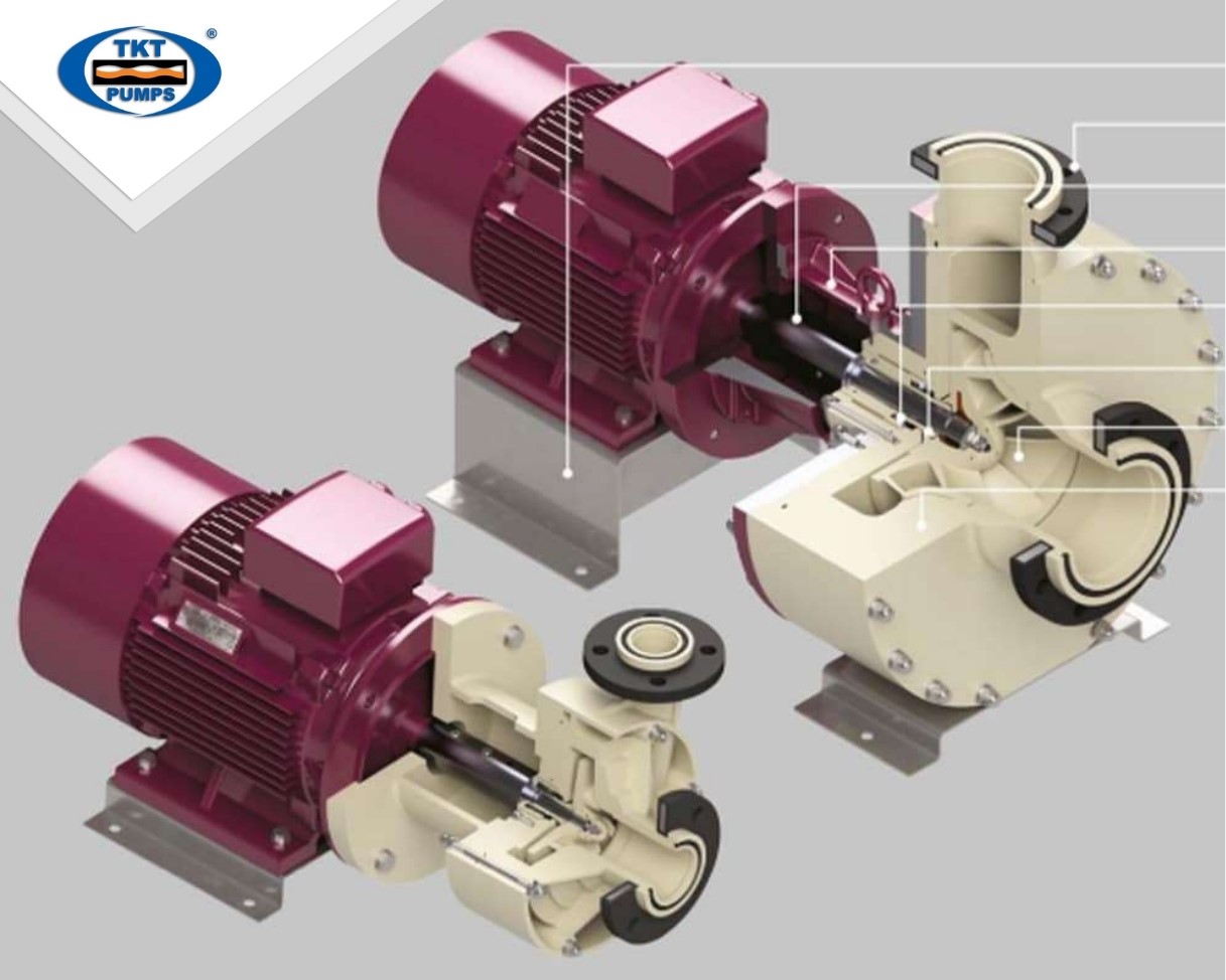
But at the most basic level, a centrifugal pump has only three components:
-
- An impeller rotates and imparts velocity to the fluid.
- A casing holds the velocity generated by the impeller and converts that rate into a steady flow.
- An assembly of mechanical components that enable the impeller to rotate within the pump housing.
In more detail, we will analyze together some of the main parts of a centrifugal pump!
Centrifugal pump impeller
The impeller of a centrifugal pump rotates rapidly to impart velocity to the pumped liquid.
If you’ve never seen a pump impeller before, picture a boat’s propeller impeller.
As the boat’s propeller rotates, it imparts velocity to the fluid around it. As the fluid moves, that velocity forces the propeller to move forward through the water.
Imagine what would happen if the boat was anchored in place, sturdy enough to prevent the ship from moving. Next, imagine that the velocity generated by the boat’s propeller is contained and controlled to create a stream of water that you can steer where you want.

What we have just described is a centrifugal pump. In a centrifugal pump, you have an impeller that rotates rapidly and imparts velocity to the fluid in the pump, like a boat’s propeller imparts momentum to the water in a lake. The shell is part of an arrangement that takes that velocity, contains it, controls it, and sends it in the desired direction. Each impeller has one or more vanes extending from the center or center of the impeller outwards in the outer diameter.
As the impeller rotates, centrifugal force causes the fluid to rush from the center of the impeller, along with the blades, and then out of the impeller at the outermost diameter. As a result, the liquid is pumped away from the circumference of the impeller at incredible velocity.
Centrifugal pump housing
The centrifugal pump housing is the pump that converts all the velocity generated by the rotating impeller into a controlled and steady flow and directs it away from the pump through the discharge point. The most common shell type is called a snail shell because it looks similar to a snail shell. The propeller is placed in the helix. However, the propeller is usually not centered in the middle.
Instead, the impeller is positioned so that the outside diameter of the impeller is closest to the curve at the intake point. This point is the point most relative to the end on the impeller called the water cutoff point. Starting from the cutting water layer, as they move around the impeller, the distance between the duct and the impeller increases gradually until they reach the intake point.
The steady expansion of the area around the impeller means that the pressure will be generated as it moves from the smallest to the most extensive clearance. The increasing pressure will push the fluid away from the discharge point.
Pump shaft
The propeller is mounted on a rod. The shaft is usually made of steel or stainless steel and is sized to support the propeller. The shafts must be carefully sized. A smaller shaft size can increase pump vibration, reduce bearing life, the potential for shaft breakage, and reduce overall pump life. However, an oversized shaft can unnecessarily increase the cost of the pump.

Suction port
Is responsible for connecting to the suction pipe to lead the water or fluid to be pumped into the pump chamber. With submersible pumps, the suction port can be free without connecting to a pipe, as they are submerged directly into the water.
Discharge port
The discharge port is designed to connect to a discharge pipe of a specified diameter. The job of the discharge port is to receive the water that is pushed out of the pump chamber from the impeller. Water will be moved through the tube, going to the location where it needs to be used.
Engine
A typical drive unit uses electricity to drive the impeller to rotate. But in fact, not all centrifugal pumps use an electric motor to generate drive. For example, in places where electricity is not available, gasoline or diesel engines or even steam turbines can be used.
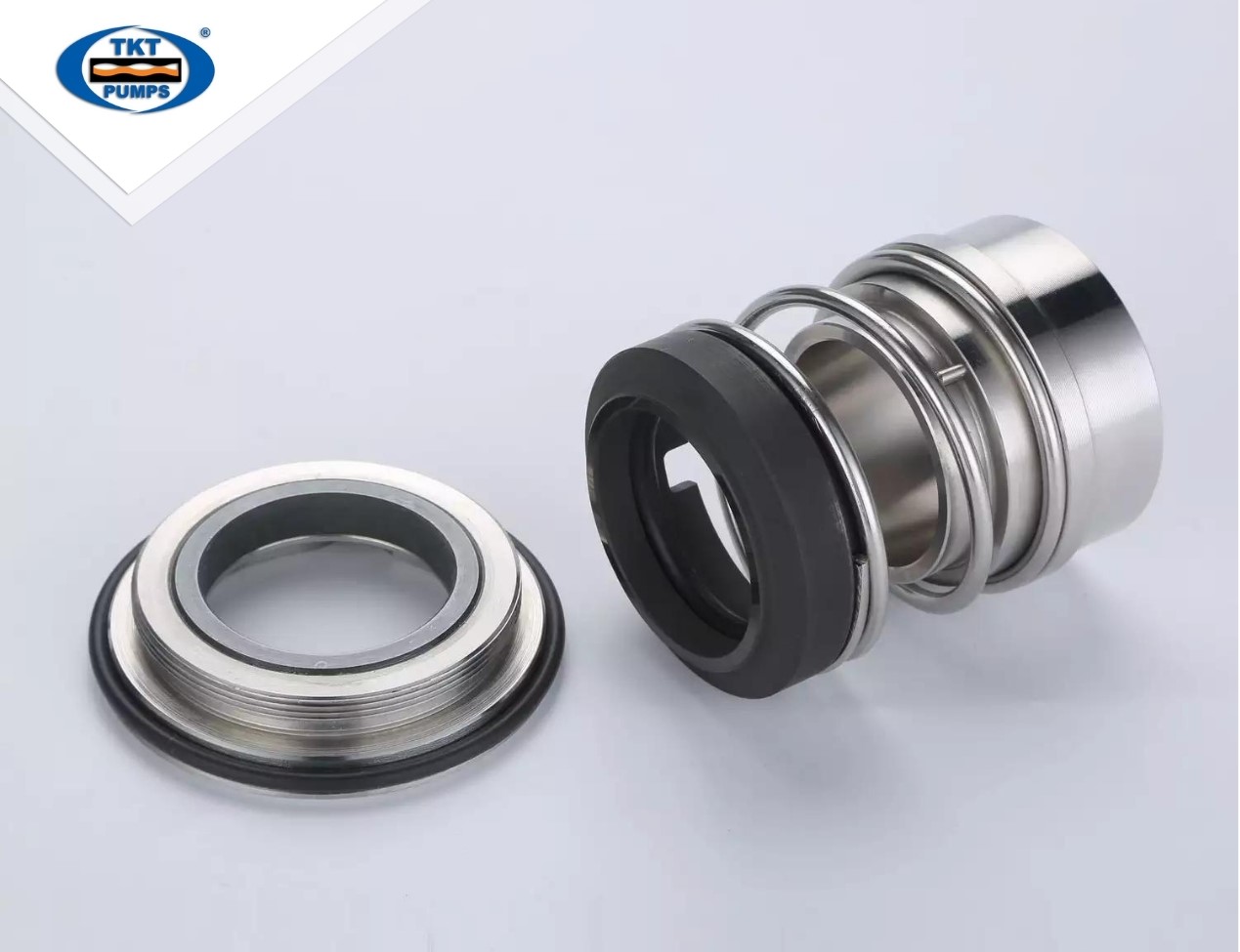
In addition, the centrifugal pump structure also has other parts such as bearings, bearings, seals, nuts …
Structure of multistage centrifugal pump
Still, the structure of the primary centrifugal pump line. The only difference on this pump line lies in the impeller, instead of only one stage impeller, also known as a single-stage centrifugal pump. The most commonly seen are household water pumps. The multistage centrifugal pump will have many impellers stacked on top of each other. What is the purpose of this multi-wing structure? The reason given was to solve the pump lift problem. Or improve head height in applications requiring high water movement. The rocket pump is a typical example of the multistage centrifugal pump model.
Structure of horizontal centrifugal pump
Horizontal centrifugal pumps will have an installation method so that the pump is horizontal to the ground. This is the most common installation that we quickly encounter in practice.

Since the pump is placed horizontally, the pump shaft also has a horizontal structure. This is the most significant difference compared to the construction of the vertical centrifugal pump. This configuration can lead to easier maintenance and repair, but the pump will take up more space. As a result, horizontal single-stage centrifugal pumps are the most common.
Structure of vertical shaft centrifugal pump
As mentioned above, the advantage of the vertical shaft centrifugal pump structure is that it does not take up installation space because it is installed vertically. And the pump motor part is located on the top so that it will be more dry and clean.
The disadvantage of this structure is that the installation must be precise, completely lying on a flat surface. However, when installed correctly, the pump will operate stably and quietly, without floor shaking and vibration.
Vertical shaft centrifugal pumps usually come with multistage impellers. Therefore, they are often used in areas that need to push water up high, used in fire protection …
The article shares with you the most detailed information about the centrifugal pump structure. Thai Khuong always wants engineering students to have a place to update their knowledge, and thaikhuongpump.com is such a place!
In addition, Thai Khuong distributes centrifugal pumps of famous brands from Europe such as Caprari, Salvatore Robuschi… If you have needs, please contact Thai Khuong immediately!


