VFDs control motor speed by varying the voltage and frequency applied to the stator of a standard AC motor. VFDs can vary speed control at startup, during the run, and at the motor stop. A standard AC motor has a published efficiency and power factor. They are quite high, typically well above 90%, but only for a sinusoidal excitation at rated frequency.
You need a variable frequency drive if you have AC motors in your facility or use mechanical means for varying VFD output.
You would need variable frequency drives even if the AC motors in your facility require a variable output.
This guide will cover everything you need to know about VFDs, including their purpose, components, types, and steps for preventative maintenance.
What is a Variable Frequency Drive (VFD)?
Variable Frequency Drive is an electronic device that can turn DC (Direct Current) into AC (Alternating Current). It also serves as a kind of electric motor controller by varying the supply frequency and voltage.
Variable Frequency Drive has some other names such as AC Drives, VFDs (Variable Frequency Drive), motor speed regulators (English is Variable Speed Drive, VSD), voltage and frequency converters (Variable Voltage Variable Frequency Drive, etc.). VVVFD)
Variable Frequency Drive (VFD) is a motor controller type that varies the voltage and frequency supplied to drive an electric motor.
VFD is also known as adjustable speed drive, variable speed drive, adjustable frequency drive, inverter AC drive, and Microdrive.
The device is usually used in HVAC systems in commercial facilities for the purpose of controlling the speed of the motor, fan, and even the compressor.
Think of the VFD as a dimmer in a light bulb. It provides the exact level of brightness you desire without having to resort to the on/off switch.
.

Electric motors are found in almost every device we use to work from small electronics, transportation, office equipment to large-scale production lines. Adjusting the speed of the motor is essential to avoid wasting energy. In factories, wasted energy and materials can pose a risk to the business, so Variable Frequency Drives are used to drive electric motors, increase productivity and save energy.
Variable Frequency Drive Operating Principle
Whilst there are a number of variations in variable frequency drive design; they all offer the same basic functionality which is to convert the incoming electrical supply of fixed frequency and voltage into a variable frequency and variable voltage that is output to the motor with a corresponding change in the motor speed and torque. The motor speed can be varied from zero rpm through to typically 100-120% of its full rated speed whilst up to 150% rated torque can be achieved at reduced speed. The motor may be operated in either direction.
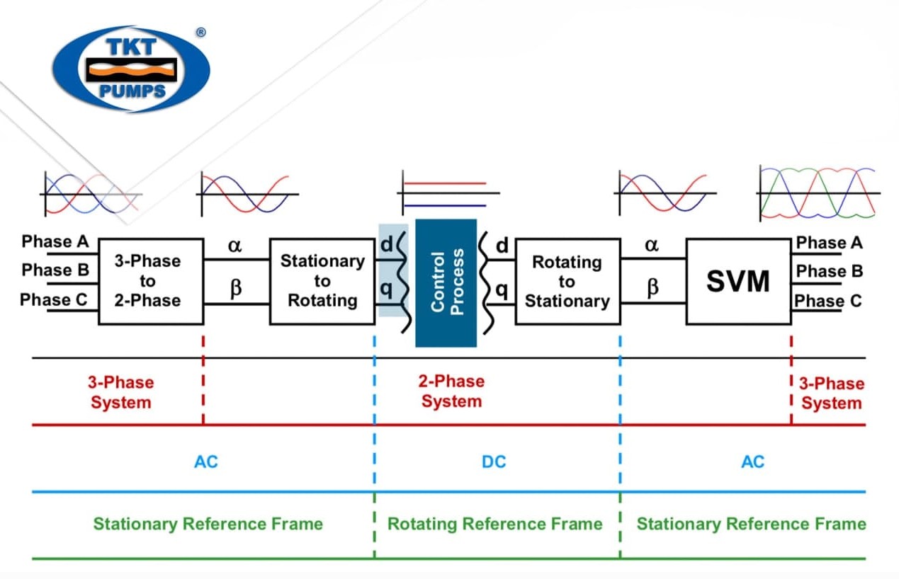
The block diagram of the variable frequency drive is shown in the below diagram:

A Variable Frequency Drive (VFD) is a type of motor speed controller that drives an Induction motor by varying the frequency and voltage supplied to the electric motor.
Variable frequency drive(VFD) mainly has a Rectifier, Intermediate circuit, and Inverter to convert back dc voltage into ac as shown in the block diagram.
Rectifier:
The supply voltage applied to the rectifier is a three-phase alternating voltage or a single-phase AC voltage with a frequency of 50 Hz or 60 Hz. The rectifier is a circuit that converts the alternating voltage into the direct voltage. Rectifiers made up of diodes and thyristors, to convert AC supply voltage into the DC.
Intermediate circuit:
The intermediate circuit also called DC-bus” or “DC-link can be seen as a storage facility from which the motor is able to draw its energy via the inverter. It can be built according to three different principles depending on the rectifier and inverter
There are three types:
1. one, which converts the rectified voltage into a direct current.
2. one, which stabilizes or smoothes the pulsating DC voltage and places it at the disposal of the inverter.
3. one, which converts the constant DC voltage of the rectifier to a variable AC voltage.

The final section of the VFD is referred to as an “inverter.” The inverter contains transistors that deliver power to the motor. The “Insulated Gate Bipolar Transistor” (IGBT) is a common choice in modern VFDs. The IGBT can switch on and off several thousand times per second and precisely control the power delivered to the motor. The IGBT uses a method named “pulse width modulation” (PWM) to simulate a current sine wave at the desired frequency to the motor.
Motor speed (rpm) is dependent upon frequency. Varying the frequency output of the VFD controls motor speed:
Speed (rpm) = frequency (hertz) x 120 / no. of poles
Variable Frequency Drive OutPut
The command from the upper stage (microcontroller IC) is sent to the output IGBT (Insulated Gate Bipolar Transistor) to convert the voltage received from the DC bus into small steps (quite similar to the principle used in the construction industry). dimmer switch). To do this, the ICs use PWM technology and convert the DC into sine waves. The longer the switching time of these waves, the higher the voltage at the output of the motor and vice versa. This process is actually responsible for two important functions – changing the output voltage without wasting power and, in particular, changing the frequency simultaneously at a certain speed to keep the torque and flux remains unchanged.

Note that the output from the VFD is a “rectangular” waveform. The VFD does not produce a sinusoidal output. This rectangular waveform would not be a good choice for a general purpose power distribution system, but is perfectly suitable for motors.
If we want to reduce the motor frequency to 30Hz, then we just need to switch the output transistors of the inverter slower. But, if we reduce the frequency to 30Hz, then we also have to reduce the voltage to 240V to maintain the V/Hz ratio. How will we drop the voltage if the only voltage we have is 650VDC?
This is called pulse width modulation or PWM. Imagine that we can control the pressure in the water line by turning the valve on and off at high speed. While this wouldn’t be practical for plumbing systems, it works great for VFDs. Notice that during the first half cycle, the voltage is ON half the time and OFF half the time. Thus, the average voltage is half of 480V or 240V. By pulsed the output we can achieve any average voltage across the output of the VFD.
Features of the Variable Frequency Drive
The inverter has the following important features:
- Overcurrent protection, especially useful while controlling high-inertia motors.
- Constant torque ensures a wider speed control range, allowing for efficient control of energy.
- The VFD acts as a barrier to input voltage noises such as harmonics, ripples, hysteresis, etc. and prevents them from entering the motor.
What are frequency converters / variable frequency drives used for?
Today, frequency converters are used practically everywhere to operate single-phase and three-phase electric motors with a variable speed. And not just in industrial environments, but in everyday life. Starting from very low power ratings to control washing machine drums up to medium power ratings for pumps used in municipal water supplies.
Variable frequency drives are used in the industrial landscape for the following applications, for example:
- Pumping, ventilating and compressing
- Positioning, processing, moving and machining

These functions are used in many industry sectors:
- Food & beverage industry
- Automotive industry
- Heating, ventilating and air conditioning (HVAC)
- Water and wastewater industry
- Paper industry
- Oil & gas
- Chemical industry
- Logistics
- Wind turbines, hydroelectric power and photovoltaic systems
- Marine

What types of frequency converters / variable frequency drives are there?
- Low-voltage converters for motor voltages in the 230 V – 690 V range (single phase, three phase – alternating voltage or three-phase voltage)
- Medium-voltage converters for motor voltages in the 2.3 kV – 13.8 kV range, especially for drive power ratings > 2.5 MW
- DC converters for DC motors comprising a controllable rectifier
- Safety extra-low voltage converters for motor voltages from 24 V DC up to 48 V DC
- Servo drive converters
What is the function of a variable frequency drive?
VFD can help to:
- Control the speed of the motor.
- Limit demand and electrical consumption of motors by reducing the amount of energy they consume.
- Decrease mechanical stress due to pressure spikes with direct online start & stop.
- Reduce the starting current of the motor.
- Protect the motor with its internal protection functions.
- Control process better
- Inherent power-factor correction
- Bypass capability in the event of an emergency
Advantages of variable frequency drives
- Large energy saving at the lower speed.
- Increased life of rotating components due to lower operating speed.
- Low motor starting current.
- Reduces noise and vibration levels.
- Reduction of thermal and mechanical stresses.
- Simple installation.
- High efficiency.

Selecting a variable frequency drive
When selecting the drive, the following criteria must be known:
- Type of motor (three-phase asynchronous motor)
- Input voltage = rated operating voltage of the motor (for example, 3 AC~400V)
- Rated motor current (guide value, dependent on the circuit type and the supply voltage)
- Load torque (quadratic, constant)
- Starting torque
- Ambient temperature (rated value 122°F [50°C])
Application of variable frequency drive
Variable Frequency Drive is used in almost all industries, but there are some common examples where VFD is most popular to use:
⇒ VFD is used to boost and control the pressure of air, gas, liquid, etc. in a booster pump motor.
⇒ VFD is used to control the pressure of air in the air compressor unit at a power plant.
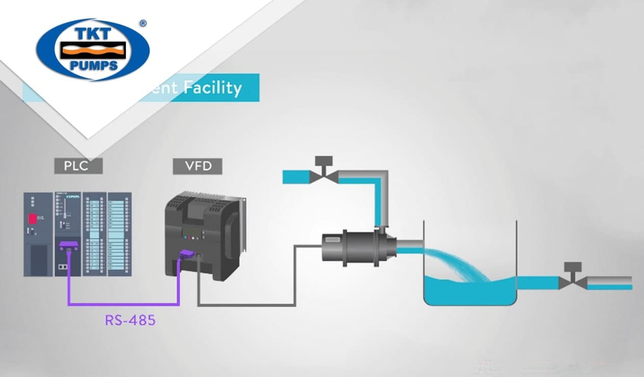
⇒ VFD is used to control the flow of water at a centrifugal pump.
VFDs (Variable Frequency Drives) can achieve reduced flow by providing variable speed pump operation. This results in reduced system pressure and operation near the pump’s Best Efficiency Point. In addition, maintenance costs might be reduced. This article will discuss the energy savings potential of variable frequency drives followed by a brief description of the operation and relative benefits of VFDs.
The most important choice to be made in choosing the VFDs is the decision to select a non-slip, solid-state VFD. Any such VFD can offer dramatic energy savings by efficiently matching the energy consumed to the hydraulic load requirements at any given moment.
⇒ VFD is used at a closed-loop control to maintain the temperature, pressure, or flow.
⇒ VFD is used at an elevator system for a smooth start/stop operation.
Electric motors in pharmaceutical industry consumes significant amounts of electricity; estimated to be about two-thirds of all usage. Even a simple air conditioning system, costing a few hundred pounds, can be expected to consume many tens of thousands of pounds worth of electricity over its useful lifetime. Variable frequency drives can help to make significant energy savings by controlling the motor speed.

The benefits of using VFDs are:
-
- Reduced downtime because gas turbines require frequent maintenance while VFDs and motors require very little maintenance. This enables more production, lower maintenance expense, and improved productivity.
- Accurate speed control and process control allowing the most optimum plant flow balance to be obtained.
- Lower energy costs because the VFD and motor has a higher efficiency than most gas turbines, especially at part load.
- Zero CO2 and NOX emissions at the operating station and greatly reduced noise. This feature often makes electric prime movers the only selection in applications near urban regions or regions with existing air quality problems.
- Independent of ambient temperature. Gas turbines generate less power when the inlet air temperature rises since the air density is reduced and less oxygen reaches the combustion chambers. VFDs and motors are not affected by temperature.
- Lower capital equipment, spare parts and maintenance cost.
- Lead times of 9 – 12 months, depending on the motor design. Compared to a mechanical prime mover which can have 18 month lead time, this shorter lead time allows for a quicker production revenue gain.

Thus, through this article. We have also understood the concepts of what an inverter is and understand the operating principle of the inverter. And especially, we know their effects, advantages as well as their applications in industry.
Thai Khuong is a pump supplier, and at present, the inverter is also a preeminent and indispensable pump control device. Do you need advice on and choosing a pump control solution? Please contact Thai Khuong immediately for help!
