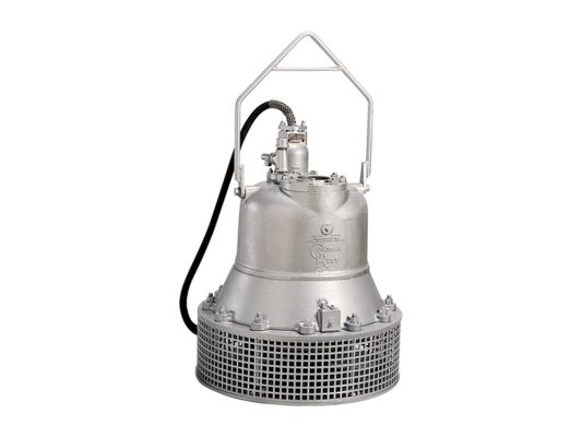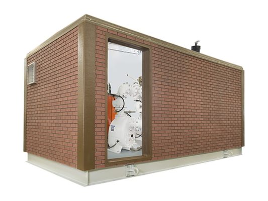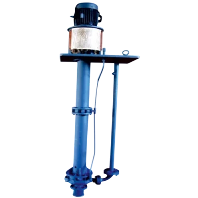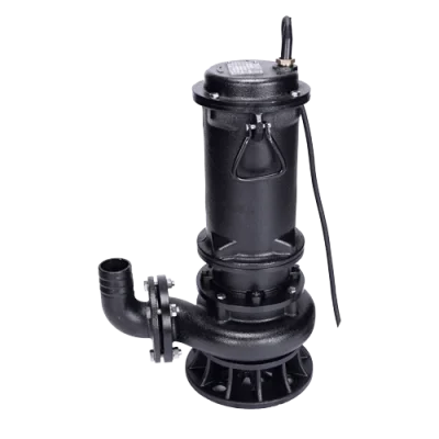




Installing a submersible borehole pump (deep well pump) correctly involves four core steps: lowering the pump assembly into the well using a stainless steel safety cable and waterproof power cable, positioning the pump deep enough so the motor is fully submerged and cooled, connecting the control panel with overload protection, and installing a dry-run protection sensor tied to the dynamic water level. Following these four steps correctly ensures stable, trouble-free operation and extends motor service life.
- Submersible borehole pump = multi-stage pump + submersible motor lowered into the well, cooled by water flowing through the motor casing.
- Select the pump by borehole diameter (inches) and total well head = dynamic water level + pipe losses + outlet pressure.
- Lower the pump using a load-bearing stainless steel cable; secure the waterproof power cable along the discharge pipe with clamps.
- Set the pump deep enough to remain submerged, maintaining clearance above the well bottom to avoid drawing in sand and sediment.
- The control panel must include overload protection, phase-loss protection, and a water level sensor / electrode for dry-run prevention.
What Is a Submersible Borehole Pump (Deep Well Pump)?
Construction and Working Principle
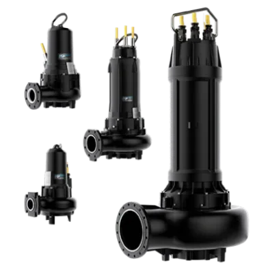
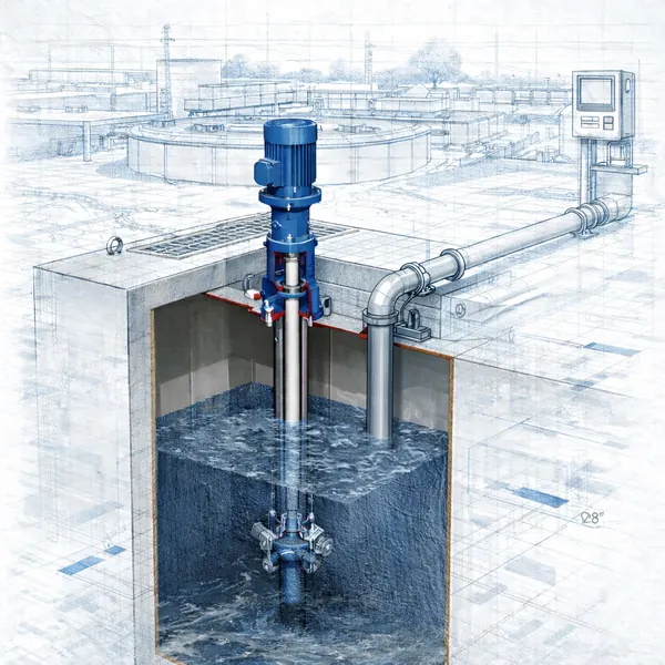
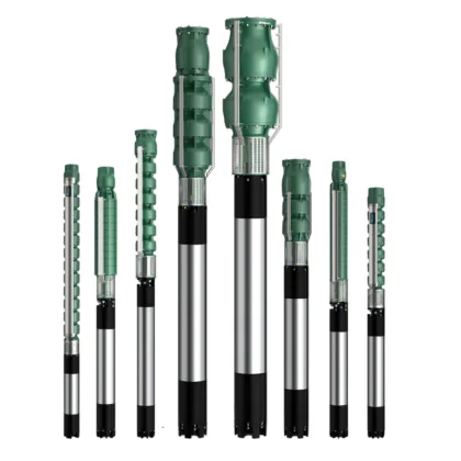
A submersible borehole pump — colloquially called a “rocket pump” in Vietnamese because of its long cylindrical body — is an assembly consisting of a multi-stage pump section directly coupled to a submersible electric motor. The entire unit is lowered below the water level inside the borehole. Water is drawn in from the bottom of the pump, passes through multiple stacked impeller stages that progressively build pressure (head), and is then discharged to the surface through the discharge pipe. The more impeller stages, the higher the head produced, making the pump suitable for deep wells.
One key point: the submersible motor is cooled by the water flowing over its casing while the pump operates. The pump must therefore always remain submerged; if the water level drops below the motor body, cooling is lost and the motor risks damage. This is why dry-run protection is virtually mandatory for this type of pump.
| Component | Function |
|---|---|
| Multi-stage pump section | Builds head through multiple impeller stages, discharging water to the surface |
| Submersible motor | Drives the pump shaft; cooled by water flowing through the motor casing |
| Discharge pipe | Conveys water to the surface and supports the weight of the pump assembly |
| Stainless steel safety cable | Safely suspends and lowers the pump; bears the full weight of the assembly |
| Waterproof power cable | Supplies power to the submersible motor down the well |
Selecting the Pump by Borehole and Total Head
Two Determining Parameters
Before installation, you need to confirm that the pump will fit in the well and match its conditions. The two main criteria are borehole diameter and total well head. Borehole diameter in inches determines which pump body size can be lowered into the casing; Caprari’s E-Series is available in multiple body sizes — E4, E6, E8, E10, and ES — corresponding to diameters from 4″ to 22″, covering everything from small domestic wells to large municipal water supply boreholes.
Total well head is calculated as the sum of the dynamic water level (the distance from the well head to the water surface while the pump is running), plus friction losses in the piping, plus the required pressure at the outlet. Selecting a pump whose performance curve passes through the required flow rate and head point ensures the system operates at the correct efficiency. When well data falls outside the standard range, consult the specifications for each specific model and the actual site conditions.
| Parameter (Caprari E-Series range) | Reference value |
|---|---|
| Pump body diameter | 4″ to 22″ |
| Maximum flow rate | up to 1,260 m³/h |
| Maximum head | up to 700 m |
| Maximum power | up to 440 kW |
Note: the figures above represent the limits of the entire E-Series range; individual models have narrower flow rate and head ranges, so always consult the catalog for the specific model and actual operating conditions.
Submersible Borehole Pump Installation Procedure
Correct Technique for Lowering the Pump into the Well
Before lowering, check the motor winding insulation resistance and confirm the correct rotation direction. Install a check valve at the pump outlet to maintain the water column and prevent backflow when the pump stops. Connect the discharge pipe section by section, simultaneously securing the waterproof power cable along the pipe with evenly spaced clamps to prevent the cable from twisting or rubbing against the borehole casing.
The full weight of the assembly is borne by the load-bearing stainless steel cable — never suspend the pump from the power cable or plastic pipe. Lower the pump slowly to the design depth: the pump must be submerged far enough below the dynamic water level to keep the motor constantly cooled, while maintaining a clearance above the well bottom to prevent sand, silt, and sediment from being drawn into the pump. Once positioned, secure the assembly firmly at the well head and seal the well cap.
- Measure and record the static water level and dynamic water level before selecting the pump setting depth.
- Lower the pump using the stainless steel cable; secure the power cable along the discharge pipe with evenly spaced clamps.
- Set the pump deep enough to remain fully submerged and maintain clearance from the well bottom to avoid drawing in sediment.
- Install the check valve and verify motor insulation resistance before energizing.
Control Panel and Dry-Run Protection
Protecting the Submersible Motor
The control panel is the critical line of protection for the submersible motor. It must include a thermal relay or overload protection set to the motor’s rated current, phase-loss and phase-imbalance protection, and an appropriate starter for the motor power rating (direct-on-line, star-delta, or soft starter depending on the model). Setting the protection current close to the actual operating value enables prompt tripping if the motor is jammed or overloaded.
Equally important is dry-run protection. A water level sensor or electrode set installed inside the well will cut out the pump when the dynamic water level drops below the safe threshold, preventing the motor from running without cooling water. Once the water recovers sufficiently, the system allows restart after a time delay. This detail is decisive for submersible motor service life.
| Protection device | Fault prevented |
|---|---|
| Overload protection (thermal relay) | Motor winding burnout due to overcurrent or locked rotor |
| Phase-loss / phase-imbalance protection | Motor running on reduced phases, localized overheating |
| Water level sensor / electrode | Dry run, loss of motor cooling |
| Check valve | Water backflow, hydraulic shock on pump stop |
Operation and Periodic Maintenance
Monitoring for Long Service Life
During operation, monitor three-phase current, outlet pressure, and flow rate to detect anomalies early. A gradual rise in current may indicate impeller wear or sand ingress; a drop in pressure accompanied by reduced flow rate suggests the dynamic water level has fallen or the impellers are worn. Avoid frequent start-stop cycling within short intervals, as each startup generates heat and high electrical stress on the motor.
Periodically inspect motor winding insulation resistance, well head sealing integrity, and the condition of the power cable. For wells with high sand content, check for wear more frequently. When replacement parts are needed, prioritize matching the original material configuration (cast iron or stainless steel) according to water quality to minimize corrosion and extend maintenance intervals.
CAPRARI · ITALY Submersible Borehole Pump Solutions
Caprari (Italy) is a centrifugal pump specialist for water supply, agriculture, and municipal applications. The E-Series is a multi-stage submersible borehole pump line (E4/E6/E8/E10/ES) with body diameters from 4″ to 22″, flow rates up to 1,260 m³/h, heads up to 700 m, and power up to 440 kW, available in cast iron or stainless steel configuration depending on the fluid. A range of submersible motors is available to complete the pump assembly for each borehole size. TKT is the authorized distributor of Caprari in Vietnam, providing configuration support based on actual borehole data.
Frequently Asked Questions
Are “deep well pump” and “submersible borehole pump” different things?
+
These are two names for the same type of equipment. “Deep well pump” (or “rocket pump” in Vietnamese) is the colloquial name derived from the long cylindrical body shape, while “submersible borehole pump” is the technical term. Both refer to the assembly of a multi-stage pump coupled to a submersible motor, lowered into a borehole to extract groundwater.
How deep should the pump be set in the well?
+
The pump must be positioned far enough below the dynamic water level to keep the motor fully submerged and cooled at all times, while maintaining a clearance above the well bottom to prevent sand and sediment from being drawn in. The exact depth depends on the measured dynamic water level and the pump assembly length, and should be calculated based on individual well conditions.
Why is a dry-run protection sensor necessary?
+
The submersible motor is cooled by water flowing over its casing. If the water level drops and the pump runs without water, the motor loses its cooling and risks rapid damage. A water level sensor or electrode will trip the pump before this occurs, making dry-run protection virtually mandatory for submersible borehole pumps.
Which Caprari E-Series size fits my borehole?
+
The E-Series is available in body sizes from 4″ to 22″ (E4/E6/E8/E10/ES) to match borehole diameters. Once the borehole diameter is known, select further by the required flow rate and total head. The range limits are flow rates up to 1,260 m³/h and heads up to 700 m; individual models have narrower ranges, so consult the catalog for the specific model.
What are the roles of the stainless steel cable and the power cable during installation?
+
The load-bearing stainless steel cable is used to suspend and lower the pump assembly, carrying the full weight of the pump; the pump must never be hung from the power cable or the pipe. The waterproof power cable supplies electricity to the motor and is secured along the discharge pipe with evenly spaced clamps to prevent twisting and chafing.
Which is more suitable — cast iron or stainless steel?
+
The choice depends on water quality. For ordinary clean water, a cast iron configuration performs well at reasonable cost. For corrosive water or applications requiring high hygiene standards, a stainless steel configuration offers greater durability for the fluid. Caprari E-Series is available in both configurations for selection according to actual conditions.
Need advice on selecting and installing a submersible borehole pump based on your well data? TKT’s technical team with 19+ years of experience and 12,000+ projects is ready to help.
Send a Consultation Request or hotline 0941.400.488
Sources: Caprari technical documentation (E-Series, submersible motors) and field installation experience; compiled by TKT.