












Metering pump calibration is the process of measuring actual flow rate and adjusting two key parameters — stroke length and stroke frequency — so that the dosing output matches the required value. The correct method is to use a calibration cylinder: run the pump for a set period of time, measure the volume drawn in, convert to flow rate, and fine-tune until the error is within ±1–3% depending on pump type. This article explains the working principle, a step-by-step procedure, and key considerations for calibration, as applied to diaphragm and piston metering pumps such as Doseuro (Italy).
- Flow rate = stroke length × stroke frequency — adjust one or both parameters.
- Calibrate using a calibration cylinder: measure actual volume over a set time interval, then convert to flow rate.
- Typical dosing error is ±1–3%; API 675 requires ±1% accuracy at steady-state conditions.
- Pumps can be adjusted manually or via a 4–20 mA signal (Doseuro SR type D/B/A supports both).
- Always calibrate at actual operating pressure, as back-pressure affects real-world flow rate.
Flow Rate Adjustment: Working Principle
Two Parameters That Determine Dosing Output
A metering pump is a positive-displacement pump that delivers a fixed dose per cycle. Total flow rate is therefore controlled by changing the volume per stroke (via stroke length) or the number of strokes per unit time (via stroke frequency). In practice, operators often hold stroke length at a stable setting and regulate flow rate primarily through frequency, or combine both for finer resolution.
| Parameter | How It Acts | Characteristics |
|---|---|---|
| Stroke length | Changes the volume per dose | Coarse resolution; should be fixed when high stability is required |
| Stroke frequency | Changes the number of doses per minute | Fine resolution; easily automated via signal input |
| 4–20 mA signal | Controls frequency remotely | Couples with pH/ORP/flow sensors for automatic dosing |
Understanding the distinction between these two parameters helps users see why the same pump can deliver very different flow rates if set up incorrectly — and why calibration is a mandatory step before commissioning.
Calibration Procedure Using a Calibration Cylinder
Calibration with a Calibration Cylinder
A calibration cylinder is an instrument that directly measures the volume of chemical drawn by the pump over a set period of time. This method is reliable because it reflects actual flow rate under real operating conditions — including fluid viscosity and line pressure — rather than relying on the nominal values stated in the catalog.
| Step | Action |
|---|---|
| 1 | Connect the calibration cylinder to the suction line, prime the pump fully, and purge all air. |
| 2 | Set stroke length and stroke frequency to the target values. |
| 3 | Switch suction from the tank to the calibration cylinder and start the timer (e.g. 60 seconds). |
| 4 | Read the volume drawn, then convert to flow rate (ml/min → l/h). |
| 5 | Compare against the target value; adjust frequency/stroke length and repeat until the target is reached. |
Perform at least two to three measurements and average the results to eliminate random error. For automatic dosing systems controlled via 4–20 mA, calibrate at several signal points (e.g. 4 mA, 12 mA, 20 mA) to build an accurate flow rate–signal characteristic curve.
Factors Affecting Accuracy
Why Actual Flow Rate Deviates from the Set Value
The actual flow rate of a metering pump depends on many factors beyond the machine settings. Air bubbles in the pump head, high back-pressure, fluid viscosity, worn check valves, or diaphragm leakage all cause dosing errors. This is why calibration must be repeated periodically, not just carried out once at installation.
| Factor | Effect | Remedy |
|---|---|---|
| Air bubbles / poor priming | Under-dosing, fluctuating flow rate | Purge air; ensure adequate suction head |
| Varying back-pressure | Reduces actual volume per stroke | Calibrate at actual operating pressure; use a back-pressure valve |
| High viscosity | Slow suction; pump head not fully filled | Reduce stroke frequency; select a suitable pump head |
| Worn valves / diaphragm | Dosing error increases over time | Perform maintenance; replace spare parts on schedule |
Typical dosing error ranges from ±1–3% depending on pump type and conditions. For processes with strict requirements, API 675 sets a target accuracy of ±1% at steady-state — commonly applied to pumps used in oil and gas and petrochemical applications.
Calibration by Pump Series
Characteristics by Drive Type
Each drive type has its own adjustment method and flow rate range, so the calibration approach also differs. Solenoid-driven pumps respond quickly and are suited to small doses; mechanical and hydraulic diaphragm pumps cover wider ranges; piston/plunger pumps handle very high pressures. The table below compares Doseuro series to help select the appropriate calibration point.
| Doseuro Series | Drive Type | Flow Rate Range | Control |
|---|---|---|---|
| SDP type S | Solenoid, PTFE diaphragm | ≤22 l/h, ≤20 bar | Frequency, fast on/off |
| SR type D | Mechanical diaphragm, motor-driven | 49–1,400 l/h, 3–14 bar | Manual or 4–20 mA, ATEX |
| SR type FM | Compact mechanical diaphragm, plastic body | 14–47 l/h, 5–10 bar | Manual, acid-resistant |
| SR type B | Hydraulic diaphragm (B & BR) | 108–1,068 l/h, ≤20 bar (AP-B up to 60 bar) | Manual or 4–20 mA, ATEX |
| SR type A | Piston/plunger, SS316L | 156–1,458 l/h, ≤20 bar (AP-A up to 230 bar) | Manual or 4–20 mA, high pressure |
| PDP | Per API 675 standard | Model/condition dependent | For oil & gas, petrochemical, LNG; ATEX |
The overall Doseuro range spans from approximately 1 l/h to 4,000 l/h; pump head material is selected according to the fluid: SS316L, PVC, PP, PVDF, or PTFE. When calibrating, always cross-reference the actual configuration against the technical documentation for the specific model in use.
Periodic Calibration Checklist
Incorporating Calibration into the Maintenance Schedule
Calibration is not a one-time operation. When the chemical, pressure, or valves change, actual flow rate will drift. A short periodic verification procedure keeps dosing stable and detects wear at an early stage.
| Item | Suggested Frequency |
|---|---|
| Re-measure with calibration cylinder | On a regular schedule and whenever the fluid or set point changes |
| Check diaphragm for leaks; tighten valves | Per equipment maintenance schedule |
| Check back-pressure and back-pressure valve | When flow rate fluctuates abnormally |
| Calibrate pH/ORP sensors and 4–20 mA signal | Per sensor manufacturer recommendations |
Keeping a record of each calibration (set values, measured flow rate, error) allows trend monitoring and proactive spare parts planning before the error exceeds the allowable threshold.
DOSEURO · ITALY Metering Pumps for Wide Ranges and Demanding Fluids
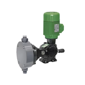
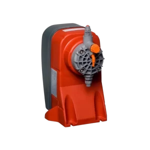
Doseuro (Italy) is a metering pump line with six product families — from solenoid SDP, mechanical diaphragm SR type D/FM, and hydraulic diaphragm SR type B, to piston SR type A and the API 675-compliant PDP series. The overall range spans approximately 1 l/h to 4,000 l/h, with manual or 4–20 mA control and pump head material selected to match the fluid (SS316L, PVC, PP, PVDF, PTFE). This varied construction allows selection of the right drive type for each chemical dosing application, from water treatment to petrochemicals.
TKT Pumps, with 19+ years of experience, 12,000+ projects, and 28+ brands, provides consultation on model selection, material configuration, and flow rate calibration guidance tailored to real operating conditions.
Frequently Asked Questions
What is metering pump calibration?
+
It is the process of measuring the pump’s actual flow rate and then adjusting stroke length and stroke frequency so that the dosing output matches the required value. The correct method is to use a calibration cylinder: run the pump for a set period of time, measure the volume drawn in, and convert to flow rate for fine-tuning.
How do you set the flow rate on a metering pump?
+
Flow rate is adjusted via two parameters: stroke length and stroke frequency. Adjustment can be done manually or remotely via a 4–20 mA signal — for example, Doseuro SR type D, type B, and type A all support both methods.
What dosing error is acceptable?
+
Typical error ranges from ±1–3% depending on pump type and operating conditions. For processes with strict requirements, API 675 sets a target accuracy of ±1% at steady-state, applicable to series such as the Doseuro PDP in oil and gas and petrochemical applications.
Why does actual flow rate differ from the set value?
+
Due to air bubbles in the pump head, high back-pressure, fluid viscosity, worn check valves, or diaphragm leakage. It is therefore recommended to calibrate at the actual operating pressure and re-measure periodically rather than doing so only once at installation.
How often should recalibration be performed?
+
Re-measure with a calibration cylinder on a regular schedule and whenever the fluid changes, the set point is altered, or flow rate fluctuates abnormally. Combine with diaphragm leak checks, valve inspection, and calibration of pH/ORP sensors and 4–20 mA signal per the maintenance schedule.
Which Doseuro series is suitable for accurate small-dose applications?
+
For small doses and fast on/off requirements, the solenoid SDP type S (≤22 l/h, ≤20 bar, PTFE diaphragm) is a suitable choice. For larger ranges, SR type D (mechanical diaphragm) or SR type B (hydraulic diaphragm) can be considered depending on the required flow rate and pressure.
Need consultation on model selection, material configuration, and flow rate calibration guidance for a Doseuro metering pump to suit your system?
Send a Consultation Request or call hotline 0941.400.488
Source: Doseuro (Italy) technical documentation and catalog specifications distributed by TKT Pumps. Compiled by TKT; technical content is neutral and provided for reference purposes.