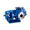
Tuthill Series 4000 Pumps
Tuthill Series 4000 Pumps – For up to 84 usgpm (318 lpm). Available with mechanical seal or packing. Capable of handling abrasive and non-lubricating fluids.
Tuthill Series 4000 Pumps – Applications Include:
Pumping lube oil
Pumping asphalt
Pumping adhesive
Pumping water treatment chemicals
Pumping glycol
Pumping crude oil
Pumping whitewater
Pumping viscous fluids
OEM pumps
Compressor pumps
Pumping polymer
Pumping paint
Model 4000 Series
4100, 4300
TUTHILL SERIES 4100
Series 4100 pumps have optional foot mounting, but can also be provided for close coupling and adapter mounting. They have an open-coring design which provides outstanding performance at higher speeds and pressures. The selection includes models with capacity range from 1/3 to 14 GPM. Rotor heads are hydraulically balanced for minimum end clearance assuring excellent priming and consistent capacity over a wide viscosity and pressure range. These pumps are capable of handling inlet pressures as high as 250 psi at standard 1750 rpm rotor speeds, with maximum discharge pressures to 300 psi
Pumps may also be provided with outboard ball bearing, tang shaft, relief valve and choice of Buna N, neoprene, Viton or EPR seal.
Series 4100 Models 4101-4108 & 4122 – 4124
Tuthill’s 4100 and 4120 pumps are available in various sizes each, with nominal capacities ranging from 0.5 to 12.9 GPM (1.9 to 49
LPM). These pumps can handle inlet pressure to 250 PSI (17 bar) and differential pressure to 500 PSI (34 bar) and have a maximum
discharge pressure of 500 PSI (17 bar). Differential and maximum pressure is limited to 300 PSI (20 bar) in model 4108. These pumps
are self-priming and particularly suited to handle liquids of 35 to 1000 SSU (2 to 200 centipoise.) Higher viscosities can be handled at
reduced speeds.
A mounting foot is available as an option, as is an internal relief valve. These pumps are bi-rotational (unless outfitted with the optional
relief valve) and designed for direct drive at standard motor speeds, with modifications available for indirect drive.
Model 4100 pumps include a mechanical seal and carbon graphite idler and housing bushings. Model 4120 pumps include an abrasion
resistant mechanical seal, carbon graphite idler bushing, ceramic housing bushing, Tutrided cover and induction hardened rotor.
TUTHILL SERIES 4300
Series 4300 pumps are provided with mechanical face type seals. Ten models provide capacities from 6 to 84 GPM. Series 4300 pumps are supplied with Woodruff keyway shafts. Pumps may be provided with outboard ball bearing, relief valve and choice of Buna N, Neoprene, Viton or EPR seal. An optional mounting foot is also available
These pumps are capable of handling inlet pressures to 250 psi at standard 1750 rpm motor speeds. Maximum discharge pressure capability is 300 psi. Maximum differential pressure capability is 150 psi.
Series 4300 Models 4312-4316
Series 4300 are flange mount pumps with mechanical seal. They are available in five sizes each with capacities from 6 to 84 GPM
(23 to 318 LPM.) These pumps can handle inlet pressure to 250 PSI (17 bar), maximum discharge pressure to 300 PSI (20 bar), and
differential pressure to 150 PSI (10 bar.).
A mounting foot is available as an option, as is an internal relief valve. These pumps are designed for direct drive at standard motor
speeds, with modifications available for indirect drive. These pumps include a mechanical seal, carbon graphite idler and bracket
bushings.
The Pumping Principle 4000 Series
Tuthill 4000 Series cast iron pumps employ the internal gear pumping principle. There are only two moving parts. Pumping action is
based on a rotor, idler gear, and crescentshaped partition cast integral with the cover. Power applied to the rotor is transmitted to the
idler gear with which it meshes. The space between the outside diameter of the idler and the inside diameter of the rotor is sealed by
the crescent.
As the pump starts, the teeth come out of mesh, increasing the volume. This creates partial vacuum, drawing the liquid
into the pump through the suction port. The liquid fills the spaces between the teeth of the idler and the rotor and is carried past the
crescent partition through the pressure side of the pump. When the teeth mesh on the pressure side, the liquid is forced from the
spaces and out through the discharge port.

Failure to follow these instructions could result in serious bodily injury or death. These pumps should not be used for handling plain
water, corrosive or abrasive liquids or liquids not possessing adequate lubricity. Do not attempt to work on any Tuthill pump installation
before completing the steps below. Disconnect the drive so that it cannot be started while work is being performed. Review the Material
Safety Data Sheet (MSDS) applicable to the liquid being pumped to determine its characteristics and the precautions necessary to
ensure safe handling. Vent all pressure within the pump through the suction or discharge lines.
All Tuthill pumps contain residual 200 SSU lube oil from the factory production test. Determine if this is compatible with the fluid you are pumping. If the fluid is incompatible, consult the factory. If the pump is to be operated at elevated temperatures, the pump should be brought up to operating temperatures gradually. Rapid or sudden introduction of liquids at elevated temperatures into the cold liquid chamber of the pump could cause damage to pump externals, seals or other internal parts. Do not run the pump dry. Failure to comply with this could cause severe
damage to the internal seal, bushings and/or metal parts. Pump needs to be Earthed separately to avoid build up of Electro-Static
Charge.
Tuthill 4000 Series pumps are required to develop 25” mercury vacuum at 0 psi on factory test. While these pumps will develop as
high as 27” of vacuum, it is a sound engineering practice to avoid extreme vacuum whenever possible. Select a pipe size to reduce line
friction loss to a minimum.
The pump should be located as close to the source of supply as conditions permit and if possible, below the level of the liquid in the
reservoir. When necessary to locate the pump in a pit, provisions should be made to safeguard against flooding. Care must be taken to
properly support the suction and discharge piping so that no strain is put on the pump due to either weight or expansion. Piping strain
can result in misalignment, hot bearings, worn couplings, and vibration. It is important that the piping used be clean and free of chips
and scales.
Relief Valve Protection 4000 Series
All 4000 Series models are positive displacement pumps. As the pump rotates, liquid is positively delivered to the discharge side of the
pump. If the discharge line is closed off, pressure will increase until the drive stalls and/or fails, the pump breaks or ruptures, or the
piping bursts.
To prevent this from happening, the use of a pressure relief valve is required. A relief valve that directs the flow back to
the supply tank is recommended. The internal relief valve available on 4000 Series pumps is designed for overpressure protection only.
It is not intended as a flow control device or for any similar use.
Continuous operation of the relief valve will result in excessive heat buildup within the pump cavity that could cause serious internal
damage. Make certain the adjusting screw of the relief valve is located on the suction side of the pump. Tuthill specifies relief valve
settings based on full-bypass pressure, where 100% of the pump flow is recirculating through the valve. It is important to know that the
valve will be partially open at pressures below the full-bypass pressure.
The difference between the partially open pressure and the full-bypass pressure is dependent on pump speed and fluid viscosity. If an internal relief valve has not been supplied with the pump some other means of protection must be utilized. These include in-line safety relief valves, pressure shutdown switches or other similar devices.
4100 Series
Unless otherwise specified at the time of order, all 4100/4120 pumps are supplied with the standard spring, with a range of 55-120 PSI
(4 to 8 bar), set to relieve at 55 PSI (4 bar) full-bypass on 200 SSU oil. The standard spring range in the 4108 is 40-70 PSI (3 to 5 bar)
and is set to relieve at 55 PSI. The relief valve setting should be reset in the actual operating condition. To adjust the relief setting within
the range of a given spring’s capability
• Remove the acorn nut (Not supplied with models 4108)
• Insert a screwdriver into the slot of the adjusting screw and hold it steady
• Loosen the locking nut with a wrench by turning counterclockwise
• Throttle the outlet line until the differential pressure at the pump port reaches the desired level
• If the pressure fails to reach this level with the throttling valve closed, turn the adjusting screw inward (clockwise) to
increase to desired pressure
• If the pressure reaches the desired level before the throttling valve is completely closed, turn the adjusting screw outward
(counter clockwise) to lower to the desired pressure
• Retighten the nut to lock the setting in place and replace the acorn nut (if supplied)
• Recheck the pressure gauge reading
CAUTION
If the adjusting screw is backed out (counter clockwise) too far, the spring and poppet could fall into pump.
4300 Series
Unless otherwise specified at the time of order, all 4310 pumps with an internal relief valve are supplied with the standard spring, with
a range of 30-225 psi (10 – 200 psi in size 2 pumps), set to provide full bypass relief at 90 psi. To adjust the relief setting within the range
of a given spring’s capability.
With a small wrench, hold the adjusting screw steady then with a second wrench, loosen the locking nut by rotating counterclockwise.
Throttle the outlet line until the differential pressure at the pump port reaches the desired level.
If the pressure fails to reach this level with the throttling valve closed, turn the adjusting screw inward (clockwise) until the desired pressure is reached.
If the pressure reaches the desired level before the throttling valve is completely closed, turn the adjusting screw outward (counterclockwise) until the desired pressure is reached. Retighten the nut to lock the setting in place and recheck the pressure gauge reading
*Technical team/consultant Thai Khuong Pumps is ready to connect to support you with information about industrial pumps as quickly as possible. Contact immediately with Thai Khuong Pumps, so we can support you better.


Reviews
There are no reviews yet.